Thursday 8 November 2018

Diamond Square Algorithm - Terrain, detail and noise generation

One type of noise generation that I haven't seen discussed much is the Diamond-Square algorithm which is an extension of the Mid-point Displacement algorithm, hence the reason for writing this. This type of algorithm in my opinion generates very natural looking noise which is suitable for terrain generation and it can also be used to generate detail on existing height-maps with realistic results without much effort. I will jump straight into it.


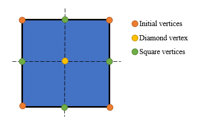
The essence of the algorithm is division and displacement at the point of division. You start with a square and split it in the middle both vertically and horizontally, doing this yields 5 new points. Once the new points are obtained height is sampled from the points around the new point and a random offset is added, this sampling is done in two steps, a Diamond step from which the center point derives its new displacement and a square step that derives the height of the other four points. Diamond step is first simply because the Square step requires the newly acquired height.


Looking at the above image showing the first Diamond step, we have derived the central point by averaging the existing four points and adding an offset R which is multiplied by the Current depth multiplier c. Essentially your c starts at 1.0f and you half it after you have finished one level of subdivision process, which is a Diamond and Square pass. The R value is a random number that has the range that you want to bind your displacement to, for instance if you wish to have terrain that spans from -4f to 4f your need a function which will return a random number R that has a range of -4f to 4f, any range can be used. I have found that using same lower and upper bounds for the range with the lower bound being negative and upper bound positive produces the best results.


In the image above is the first Square step, we need to work out the n1-4 displacements and this is done by taking the points that are adjacent horizontally and vertically to the point that we wish to evaluate. There is a little trick when dealing with the border points and in the first Square step all of the new points are border points. We are missing a value which I have designated X above, there are two ways to solve this. Simple solution is to make X = C, the more interesting approach is to make X=n3 when working out n1, X=n4 when working out n2 and so on. Problem there is that if you are working out n1 and need n3, n3 needs n1, to solve this I pass n3 all the values that n1 is using and use that to calculate the averaged midpoint before adding the offset, the new n3 value is then used to set n1 = n3. This method produces wrapping of the noise/height map on all four sides.

The above two steps are repeated until you have reached the level of detail that you desire. And that might even be enough to get you going, but there are some details that are essential for producing height-maps without artifacts, have a look at the mapping below as we head into the third level of detail. Initial points are Orange, first level pass is Green, second level pass is Yellow, Red is the Diamond step of the third level and Purple is the Square step of the third level.


It's pretty obvious that our new Red and Purple points are dependent on both their level and the levels above them for their midpoint average calculation, if we don't at least nudge the calculation in the right direction, artifacts appear, they manifest as small dimples in the height-map that are more pronounced if you make a 3D model out of the data. During the Square step (the easier one to correct) the level of adjacent points depends on the x value of the position you are evaluating, if x%2=0 the top and bottom values are of previous level and if x%2=1, left and right are of the previous level. It's a bit more complicated for the Diamond step I won't go into detail and will rather post the code below, but the level is dependent on both the x and y position of the point being evaluated.

float hlt = data[x, y];
float hrt = data[x + 1, y];
float hlb = data[x, y + 1];
float hrb = data[x + 1, y + 1];

float add = 0f;
if (y % 2 == 0)
if (x % 2 == 0) { add += hrb + hlt; } else { add += hlb + hrt; }
else
if (x % 2 == 0) { add += hrt + hlb; } else { add += hlt + hrb; }

float mid = (hlt + hrt + hlb + hrb + add) / 6.0f;
float offset = (this.rand.GetHeight() * this.cDeviance);


The resulting formula doubles the values of the the heights that were a level above and averages them over 6 points instead of 4, this is true of the Square step adjustment too.

The beauty of this algorithm is that you can take a map of any resolution and increase that resolution believably by only having to adjust the R range and if you need to, the seed for the function that returns R. I think that's about it, a C# Unity implementation link is below, hope you find this useful.

https://pastebin.com/Bm4nscyE

Wednesday 6 December 2017

PYPEM - Public yet private email

Idea behind PYPEM is to have an email system that functions in the public domain while remaining secure and private. The assumption is that trust is not required and that messages can be left anywhere without the fear of an unintended recipient reading it. For instance encrypted messages can be left in open view on public forums, shared via insecure communication channels or printed onto physical media, if the communication location is shared by parties beforehand, not even the recipients address needs to be revealed. What follows is a high level overview of how the system functions.

Concept

Each client has a RSA key-pair, the public key is used as the address of the client. When sending an email message to somebody, the public key is used to encrypt a random AES key phrase that will be used for that particular email. The recipients public key is prefixed to the message and serves as an identifier to who the email is addressed to, however it is not necessary to include this information if the recipient knows that the message is for them. Once the recipient has the message, the AES key phrase is decoded with their private key and the rest of the message it decoded with that phrase.

Guarantees

Since anybody that has the public key which serves as the address of a client can send a message to any public address, RSA hash signing is used. This ensures that the sender was in fact the one who encrypted the email. Also it's impossible to read a message that's encrypted with someone else's public key. This guarantees that the sender and receiver are the only ones who are capable of communicating with each other. Another layer of security is the pairing that takes place, when the first exchange of messages takes place, the communicating parties give each other a secret passphrase that is used for all subsequent messages.

Server

Server is there to provide a centralized message storage and retrieval capability, the server actively ensures that each email transaction is current, this is done by the server requiring the sender to return a random passphrase that is encrypted using the sender's public key. Since only the party with the private key that corresponds to the public key that is claimed to be sending the message can decode the passphrase it's guaranteed that the sender is legitimately sending the message in real time.

Conclusion

An attacker could never read an email that is not intended for them and he can never pose as a sender of an email that he is not the sender of. The only thing the user needs to ensure is that he has the correct address for his contact.


PYPEM is currently available on Google Play store.


Monday 31 August 2015

Procedural city generation in Unity3D

I have been fiddling with procedural generation for a while now, a few months back I was working on a Procedural City Generator in Unity3D and after publishing a video on youtube, a few guys suggested that it would be a good idea to make a tutorial about this. So this is my first tutorial and I will try to explain my method of generating a city.

Basic theory is as follows, roads need to be generated in such a way that they look somewhat realistic and buildings need to be placed besides the roads. I use a subdivision algorithm for road generation, in essence the first few roads are pre-defined, they influence the overall look of the city. All other roads are generated by division of existing roads. For buildings, I just test a position besides the road to see if it already contains a building, if the new building does not collide with an existing one, the spot is taken and the next road-side position is evaluated.

I have just realized that posting all the code here for each class is really not practical, so I will discuss the generation approach rather than explain the code, line by line.

In Unity, there are some logical structures that need to exist in order to render and keep track of everything. The minimum implementation needs a road generation class, a road renderer class and the building placement class.

For the roads I use RoadPoint, RoadSegment and Intersection classes to represent the RoadNetwork of the city. RoadPoint has just a Vector2 position point and a RoadSegment reference of its parent, so it knows who it belongs to. A RoadSegment consists of two RoadPoint, one for each end of the road that it represents and a few helper functions. And finally an Intersection just has a List of RoadPoint that make that intersection, the list is sorted in circular order when the intersection mesh is created.


RoadRenderer is pretty simple, it just needs to be able to render an Intersection and a RoadSegment. Since we only have 2 points for a RoadSegment and we need to create a road Quad that has width, I take the perpendicular vector at both RoadPoints to get the new RoadSegment Quad. Applying the texture to a RoadSegment can be done in two ways, you can set your texture tiling to repeat and adjust the repeat vlaue of the texture per Quad, according to the length of the RoadSegment or you can split the segment into many Quads and apply the texture to each one.


Intersections are a bit more tricky, in my prototype I only have intersections that are four points or less, I think the method can be used to create intersections with more points, but I have not tested it. First off we need to find the real points of the road that connect to the intersection, same way as when creating RoadSegment Quads. This will result in 8 points or less, 2 per each RoadPoint that is part of the Intersection, to keep things simple and it works well enough, I just  sort the points in circular order and create a Intersection Quad/Mesh from those points. The example below is pretty ugly as the roads are coming in at different angles, but it still works. It's also possible to merge the vertices within some threshold to get a clean Quad, but this might affect your road thickness if using a single Quad as the whole RoadSegment.

Road Network Generation


So now that we have the structures required to represent the city road network, it's time to generate that network. General algorithm is pretty simple, we take an existing RoadSegment and split it somewhere around middle, we create an intersection at the splitting point, and now have two road RoadSegment from the existing one and an Intersection. From that new Intersection we extend a new RoadSegment perpendicular to the old segment. Once we have the new segment, we check if that new segment intersects any other existing segment, if it does, we need to create an Intersection for each intersect and split the intersecting segments to reflect the new connections.


So looking at the picture above, we split the Current Segment somewhere between 45-55% of the segment length. Then we added an Intersection that consists of 3 points, 2 points are from the Current Segment and 1 point is from the New Segment. We then found that the New Segment intersects some arbitrary Existing Segment and now we need to create a new Intersection with 4 points and split both the Existing Segment and the New Segment. The new Intersection will have 4 points, 2 from the New Segment and two the Existing Segment.

That is the base, however there are a few other things that are needed to generate a somewhat realistic structure. First off I assign the RoadSegment a level value, so the blueprint roads that are added are level 0, each time a new RoadSegment is spawned from an existing one its level value is increased. This allows you to have a road hierarchy and it can be used to make the lower level roads thicker, buildings that sit on the lower level roads can be bigger and you can split the RoadSegments based on their level. I split level 0, 1 and 2 twice and then level 3 once in my generation prototype. 

Also you can decide, based on some probability if you will just add a three-way intersection when you split the segment or a four way intersection. You should have code to add two perpendicular new segments as this is nearly essential for getting the look right.

Building Placement


This is pretty simple, for each RoadSegment two positions on opposite sides perpendicular to the road are evaluated at increments. Each position is checked to see if it can hold a building, in my implementation I adjust the buildings a little, their width and length before moving on to the next road-side position. It is possible to check if an existing building mesh will fit, the buildings need not be simple boxes. A new Building placement needs to check that it does not intersect a RoadSegment and it needs to check that it does not intersect any other Building, if those conditions are met, a building is placed in the allocated position.

Conclusion

I know this is a high level explanation of the method used so I have included below the download to the Unity3D project files. Do note that the source was not meant to be shared, so there might be some unexplained functions and unexplained code. At the time intention was to make a functional prototype.

Current generation algorithm is about 5-10x faster than the one shown in the youtube video below.

 
City Generator - Unity3D Source
GitHub Link

Wednesday 21 January 2015

Bucket Based Compression for Data Transmission

This approach to transferring more information than what is being transported is not time based, it's also possible to achieve much more stable and higher transmission rates.

A basic scenario is as follows, a person is given a binary stream of bits that needs to be transferred over some distance, we can say that each bit is a colored ball, a black ball is a binary number zero and a white ball is a binary number one. At the destination, another person has placed four buckets, each bucket is numbered with one of the four possible combinations of two bits, 00-01-10-11. 

The person that is transmitting data takes the first 3 balls from the stream that he is given. The procedure for getting those three bits over to the destination is simple, the first bit is thrown into a bucket that has the same label as the next two bits. For instance if the three balls are black, black, white (001), a black ball is thrown into the second bucket (01). The receiver just checks what color the ball that has arrived is and appends the bucket label to it.

In this instance one ball has been thrown and three balls worth of information have been received. The transmission to transportation ratio is 3:1, that is a 66% compression rate, something that is very hard to achieve with file compression. And this method is independent of actual data. 

Best thing about this approach is that the compression scales upwards with more buckets, so for every 2n buckets you get n bits of compression. With 128 buckets you get 7 bits of free data, that is a 8:1 transmission to transport ratio, with only 12.5% of data actually being transported, you are transferring 8x more data than what is being sent.

Problem with this is that I can't think of a way to adopt this to TCP/IP transmission, there are a few reasons, first the TCP/IP packet already contains the port number that would be used as the bucket number, thus there is no real compression as you are just compressing the packet information. Second reason is that a TCP/IP packet's minimum size is over 128 bits, that means that the ratios would be at 128 bits instead of one, so with 128 buckets the compression gain would be at around 6% instead of 800%.

Sunday 6 July 2014

Time Based Compression for Data Transmission

I have been working on random data compression for a few years now, my hobby project, it's been mostly a brute force attempt to steal a bit from a randomly generated data stream. I do realize that recursive compression of data is theoretically impossible, what keeps me going is the belief that random data is just a particular type of data; meaning that randomly generated data is only a subset of all data, if this is true then compression of this data becomes possible.

Since years have passed on this project and I have nothing to show for it but better knowledge and some logical tools and tricks at bit level; I have recently decided to shift my focus to something a bit more possible, compressing random data once during transport. 

Trick being that time itself can be used to transfer more data than what is sent. For this to work, we need a synchronized clock at the source of transmission and another one at the destination and a some estimates of transmission delays.

We can use different number of time windows to send "invisible" bits into. Working with two time-frames we have a saving of 1bit for every 1bit that is transmitted; that is a saving of 50% on the amount of data being sent.


The way this works is the following. We get two bits at a time from the input stream and then send the second bit in the first bit's time window. The four possible values for two bits are 00,01,10 and 11. If the first bit is 0 we send the second bit into the first time window, otherwise we send the second bit into the second time window.

At the receiving end the receiver checks it's clock and determines at what time-frame the data arrived; the transmission delay should be considered, I'm assuming minimal delay in the example. If the data arrived at time-frame 0 a 0 is enqueued followed by the data that has arrived. Otherwise a 1 is enqueued followed by the data. This yields two bits of data for every bit that is sent.

The way this is at the moment is very hard to use for things such as network transmission, it could probably be implemented for on-board systems with little trouble, systems that have a synchronized clock running and that have small stable latency variations. 


The current code is proof of concept and can be optimized. Also, in this example there is no increase of transmission speed, because two time-frames expire before two bits of data are collected. However if the time-frame is reset after the first bit, there is a 50% chance (considering random data) that two bits will be transmitted in one time-frame, thus increasing the transfer rate.

Code below is C# using VS2013.

/// <summary>
/// Time Based Compression for Data Transmission
/// by Sasha Adamovic 
/// 2014
/// sasha.adamovic@gmail.com
/// </summary>
using System;
using System.Collections.Generic;
using System.Linq;
using System.Text;
using System.Threading.Tasks;

namespace timeCompression
{
    class Program
    {
        const long timeWindow = (long)(TimeSpan.TicksPerMillisecond * 5);
        const long halfWindow = (long)(TimeSpan.TicksPerMillisecond * 2.5);

        private Random rnd = new Random((int)DateTime.Now.Ticks);
        private long total = 0;

        static void Main(string[] args)
        {
            Program app = new Program();

            while (true)
            {
                Queue<bool> dataToSend = new Queue<bool>();

                //get some data
                for (int i = 0; i < 1024; i++)
                {
                    bool bit = app.rnd.Next(2) == 0 ? false : true;
                    dataToSend.Enqueue(bit);
                }

                //store original so we can check it
                Queue<bool> original = new Queue<bool>(dataToSend.ToArray());
                Queue<bool> result = new Queue<bool>();
                
                //count the number of bits sent, just to be sure
                int bitsSent = 0;
                while (dataToSend.Count != 0)
                {
                    //check the first bit
                    if (!dataToSend.Dequeue())
                    {
                        //wait for proper time-frame
                        while (DateTime.UtcNow.Ticks % timeWindow > halfWindow)
                            ;

                        //send one bit
                        app.sendData(dataToSend.Dequeue(), ref result);
                        bitsSent++;
                    }
                    else
                    {
                        while (DateTime.UtcNow.Ticks % timeWindow < halfWindow)
                            ;
                        app.sendData(dataToSend.Dequeue(), ref result);
                        bitsSent++;
                    }
                }
                //add to running total
                app.total += bitsSent;
                app.total -= original.Count;

                //check data
                for (int i = 0; i < original.Count; i++)
                    if (original.Dequeue() != result.Dequeue())
                        Console.WriteLine("!!!!!!!!!!");

                //show off
                Console.WriteLine("saving:" + app.total + "bits");
            }
        }

        /// <summary>
        /// send/recieve a bit, then append to data
        /// </summary>
        /// <param name="bit">bit being sent</param>
        /// <param name="result">result</param>
        private void sendData(bool bit, ref Queue<bool> result)
        {
            if (DateTime.Now.Ticks % timeWindow < halfWindow)
            {
                result.Enqueue(false);
                result.Enqueue(bit);
            }
            else
            {
                result.Enqueue(true);
                result.Enqueue(bit);
            }
        }
    }
}